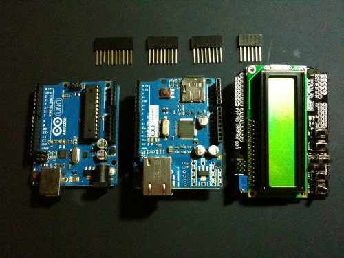
I just bought LCD shield from dfrobot.com, and want to use it as a display screen of my arduino uno. So far, the tiny web server project on my uno works properly with ethernet shield, i can create a simple http request from my laptop, and uno will process that request. For this case, i will build a simple counter module inside the webserver and display it on the lcd screen, very easy stuff.
So, for the preparation i will need one uno board, one ethernet shield, one lcd shield, and some extended male/femail pin connectors.
I need the extended pin connectors, to extend the high of the lcd shield. I found that the lcd shield have small legs, but remember these legs is enough fit for arduino board only. But the problem was after i applied the ethernet shield on the top of the arduino uno, the lcd shield cant be fit to plug anymore, as you can see here the RJ45 female connector is the problem, it was very tall.
Ok, the stack is done. Let’s move to validate the pins connector, is all the pins are valid? start from arduino pins until the lcd shield pins. Between arduino uno and etherent shields there are 4 pins reserved, means that the other shield shall not these reserved pins, it will be conflict pin data. These pins are pin 10 for ethernet module selection, pin 11/12/13 for SPI bus connection. Between arduino uno and lcd shields there are 7 pins reserved, please find the following pins below
So far, I found there is one conflict pin 10! Sigh. Pin 10 is very important for ethernet shield and it must be used, the inside the ethernet shield itself there was another module as to read and write to sd card, both modules used the same SPI bus to communicate from/to arduino board, and the problem is only one SPI bus provided by arduino board. So both modules must share the SPI connection, can use the one simultaneously. To cover this problem, that’s why pin 10 is used as selection module. But luckily, pin 10 on lcd shield is not important because it only used for backlit control, yippee! So, I decided to take out the pin 10 on the extended pin legs, like the following this picture below.
The hardware parts is done, lets move on the sketches. I will use the dhcp service from my laptop to generate the local ip of the arduino board, so that is why i only type the mac address, no signing ip manually, and i will use “EthernetServer” as simple tiny webserver module.
[gist https://gist.github.com/3904071 /]Arduino team always makes a good job for the library, inside the lcd library u can just easly defined with statement “LiquidCrystal lcd( 8 , 9 , 4 , 5 , 6 , 7 )”, the numbers in the brackets are the pins location. Lcd shield that u find in the market can be variant from the many vendor side and the screen total characters, that is why so far there is no standard pin allocation, in order to make it flexible the lcd shield library must required array of pins as input parameter. To start the lcd, i can just type “lcd.begin( 16 , 2 )”, this statement to initialized how many row characters and col characters that support by the lcd shield, in this case i only have 16 x 2 characters.
To handle the client http request, i just copied the sketches from previous blog as a base, and put the additional last statement “lcdPrint( 0 , 1 , String( totalRequestor++ ) )” to increase the counter every time the request is processed and display the counter into the lcd shield, very easy kid stuff! Next time i plan to use the lcd shield to display my tweeter message, for sure.
Ok the sketches is done, compile, plugged all the cables, and run.
Make sure the tcp connection is well established, and validate the ip address.
Everythings is ok now, and trying to do the simple http request 5 times from the web browser and lets see how the lcd counter looks like below pictures.
Done :-)


Thank you, I loved this post. For future googlers: at some point, you will want to use also pin 10. This is not a problem: find a spare electronic cable (I used a cable bringing power from a round jack to a small circuit board, but battery cables would work as well, as well as stereo red/black cables – just pick the black one), remove 1 cm of rubber from both ends, wrap 1 end around pin 10 (from the part that stays outside the header), and wrap the other end around either A4 or D3 pins, right before putting them into the headers. Use A4 if you don’t mind about PWM (ie, no analog backlight control, just on/off). Use D3 is you want analog control of backlight (256 steps.)
At that point, put this in the setup:
pinMode(D3, OUTPUT);
digitalWrite(D3, HIGH);
and use digitalWrite or analogWrite to control the backlight.
also, why letting D10 stay *outside* the box? I bent mine inside, so it doesn’t interfere with other cables, or with the lego box a made for the “thing” :)
cheers
berlingozzo
can you send me the code to tomasapostolsantiago@gmail.com please
good project
bye
can you send me the code to jorge.saniagarcia@gmail.com please
Good Job
Very well done!
Con you send me the code too? jessietercero@yahoo.com.ph
I hope this is still active page. Thanks!